


In-Vehicle Performance Validation of the Semi-Active Hybrid Energy Storage System
By: Habib-ur Rehman
Introduction
A hybrid energy storage system (HESS) consisting of high-energy-density batteries and high-power-density Ultra-capacitors (UCs) can perform better than a battery alone powering an Electric Vehicle. Hybrid energy storage can harness the benefits of the battery and UCs together and meet the energy storage as well as a vehicle’s power flow requirements. Recent research has focused on a variety of HESS circuit design topologies [1]-[4] and power management and control [5]-[6]. The passive, semi-active, and active HESS configurations have gained significant attention.
The semi-active topology is the preferred choice due to its reduced circuit complexity and price compared to the active hybrid configuration, and for its better performance when compared with the passive hybrid configuration. In the semi-active topology, UCs power the traction motor directly, and batteries with mass amount of energy storage are connected in parallel with UCs through a bi-directional DC-DC converter. The UCs supply the dynamic component of the load current which decreases the battery size, limits the battery peak current, and extends its life. The UCs can be charged by the batteries when necessary, and vice versa. Most of the recent work on the subject of HESS [1]-[3], [5]-[6] either presents the simulation and analysis of various HESS topologies or validates their feasibility on a test bench. However, this article describes the actual implementation of a semi-active HESS and demonstrates its performance in the Ford European Mondeo for the Integrated Starter Alternator (ISA) application. The Mondeo HESS is designed with a 48 V battery connected through a bi-directional DC-DC converter with 300 V UC bank which powers the ISA motor. The semi-active HESS topology also enables the flexibility of powering the motor at a higher voltage while operating the battery bank at lower voltage. Thus, the work presented in this article also presents a design for the future potential 48 V automotive power net required for meeting the ever increasing energy demands of the vehicle.
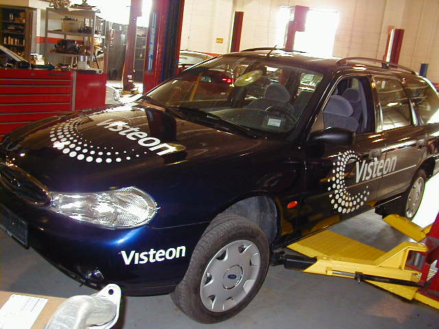
Fig. 1: Ford Mondeo with semi-active HESS based ISA system
Performance Validation of HESS
Figure 1. shows a Ford Mondeo for which the prototype semi-active HESS shown in Figure 2 was designed, developed and implemented.
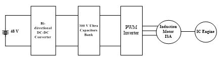
Fig. 2: HESS and ISA system configuration
The system includes a 48 V battery and 300 V UC bank powering the induction motor that is designed to provide a minimum of 150 Nm starting torque at 150 V. The UCs also gives the flexibility of operating the motor with a variable voltage. The lower limit of UCs voltage is set at 150 V due to the fact that further decrease would make the motor fail to meet the torque threshold of 150 Nm required for the starter operation. A 300 V UC bank is designed so that existing and well established 250-300 V AC machine technology can be leveraged, instead of developing a relatively new 48 V machine design. The UCs source and sink the high power flow and ease the stress on the 48 V battery. A detailed discussion on the starter alternator and its integration in the vehicle can be found in [7].
The proposed semi-active HESS in Figures 3 and 4 for ISA application was experimentally validated during an actual road test drive. The UCs voltage limit during these tests is set to 250 V. Figure 3 (a) shows that the DC bus voltage drops during the starter operation which is realized by a positive torque command current Iq. The actual and command currents are plotted in Figure 3(b).
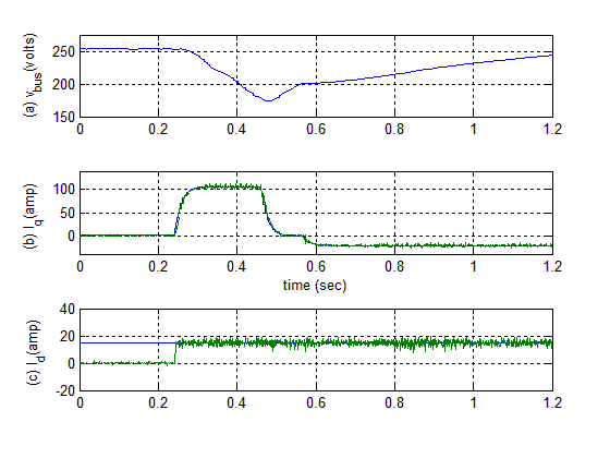
Fig. 3: Semi-active HESS system operation in the vehicle
The system is switched to generation mode after the engine compression starts at 500 rpm. This can be observed by a negative torque command current at about 0.58 sec which charges the UC bank back to 250 V in about 0.6 sec. Figure 3 (c) shows the flux command current Id which is adjusted for optimal machine efficiency. The UCs during this regeneration process once fully charged will start storing the energy in the battery through the bi-directional DC-DC converter. Conversely, the UCs can be charged by the battery in case the starter action is required and the UCs voltage is below the preset limit. Figure 4 (a) and (b) show the engine rpm and the rotor angle θ, respectively, during the starter operation.
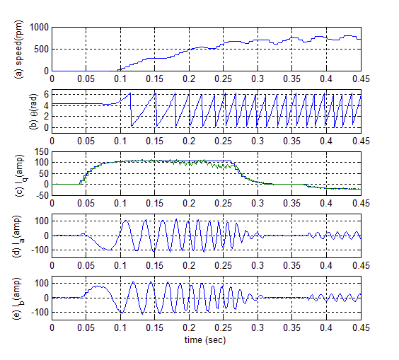
Fig. 4: Semi-active HESS based drive system operation in the vehicle
The Figure 4 (c) shows the torque command current Iq, while Figure 4(d) and (e) show that motor draws about 100 A current for the starter operation. All types of AEVs, especially during urban driving, are subjected to frequent and rapid charging/discharging cycle due to repetitive start/stop function at the traffic signals, acceleration/deceleration of the vehicle, and sudden braking. The semi-active HESS system designed in this work is well suited for such operations and for protecting the battery life.
Conclusions
The implementation of a semi-active HESS for a prototype ISA in an economy class vehicle has been demonstrated. The proposed HESS runs the starter alternator functions effectively and also protects the battery from frequent and impulse charging and discharging. The system proposed in this work also gives the flexibility of running the traction motor at 250 V while the battery pack operates at 48 V. The in-vehicle implementation and performance validation of the semi-active HESS presented in this article present a way forward to the automotive industry for adopting such HESS in the future production AEVs at large, and micro hybrid vehicle with potential 48 V battery in particular.
Acknowledgment
The author would like to acknowledges the contributions of Mr. Ning Lu, Mr. Gurinder Kahlon, and Mr. Robert J. Mohan of the Visteon Automotive Systems in the development HES in the prototype vehicle.
REFERENCES
J. Cao, and A. Emadi, “A New Battery/UltraCapacitor Hybrid Energy Storage System for Electric, Hybrid, and Plug-In Hybrid Electric Vehicles,” IEEE Trans. on Power Electronics, vol. 27, No. 1, pp. 122-132, January 2012.
A. Khaligh, and Z. Li, “Battery, ultracapacitor, fuel cell, and hybrid energy storage systems for electric, hybrid electric, fuel cell, and plug-in hybrid electric vehicles: state of the art, ” IEEE Trans. on Vehicular Technology, vol. 59, No. 6, pp. 2806-2814, July 2010.
A. Kuperman, I. Aharon, S. Malki, and A. Kara, “Design of a semiactive battery-ultracapacitor hybrid energy source,” IEEE Trans. Power Electronics, vol. 28, no. 2, pp. 806–815, Feb. 2013.
J. M. Blanes, R. Gutierrez. A. Garrigos, J. L. Lizan, and J. M. Cuadrado, “Electric vehicle battery life extension using Ultracapacitors and an FPGA controlled interleaved buck–boost converter,” IEEE Trans. on Power Electronics, vol. 28, No. 12, pp. 5940-5948, December 2013.
O. Laldin, M. Moshirvaziri, and O. Trescases, “Predictive algorithm for optimizing power flow in hybrid ultracapcitor/battery storage systems for light electric vehicle,” IEEE Trans. on Power Electronics, vol. 28, No. 8, pp. 3882-3895, August 2013
B. Hredzak, V. G. Agelidis, and M. Jang, “A model predictive control system for a hybrid battery-ultracapacitor power source,” IEEE Trans. on Power Electronics, vol. 29, No. 3, pp. 1469-1479, March 2014.
H. Rehman, “An integrated starter-alternator and low-cost high-performance drive for vehicular application,” IEEE Trans. Vehicular Technology, Vol. 57, No. 3, pp 1454-1465, May 2008.
About the Newsletter
Editors-in-Chief

Jin-Woo Ahn
Co-Editor-in-Chief

Sheldon Williamson
Co-Editor-in-Chief
TEC Call for Articles 2023 - Advances in Charging Systems
The TEC eNewsletter is now being indexed by Google Scholar and peer-reviewed articles are being submitted to IEEE Xplore.
To submit an article click here.