


Vertical Transportation: Modern VVVF Drives and PM Machines
Anand R, M. Mahesh
Introduction
The universe and the world that we survive in now will almost certainly be impractical had it not stood for innovations in transportation. The Ward-Leonard drive system for DC Motors was invented in 1893 and 100 years later the Variable Voltage and Variable Frequency drives (VVFDs) for AC Motors came to existence for vertical transportation. During the past 30 years, the use of AC variable voltage and variable-frequency drives has grown, and for many they have become the preferred way of controlling vertical transportation traction machines. The advantages are well documented and include increased system efficiency, simplified commissioning and improved ride quality. Increasingly, the issue of power quality on the electric system is becoming a point of concern when selecting and sizing elevator systems.
Vertical Transportation:
The focus to work on elevators has become more prominent and critical; the areas which need analysis are adjustable speed motor drive and its performance analysis to the latest trend of Brushless Direct Current Motors or Permanent Magnets Synchronous Motors (PMSM) [1]. In the present scenario where the world is heading to sky scrapers and is going extra vertical, the elevator has become the most basic common essential and mandatory requirement that contributes to about 6-10% of total energy consumption of the building. [2-5]
It should also be noted that since there is a lot of adjustable speed drives (ASD) adopted for the preciseness to control the speed profiles, accuracy in deceleration, improvement in the time taken for the travel when it responds to a call from start to stop, which indeed generates lots of harmonics and fed back to the supply source, the measure of harmonics is also being studied with the existing system with a prototype system integration, this would help the people in the society for optimization and effective utilization of energy, especially focused more for urban areas in our country. Fig.1. represents general taxonomy of the elevators, which are generally classified based on the requirements by the buyers that are driven mostly on the occupancy and movement of men and materials in the buildings.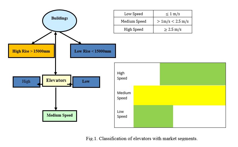
The reasons behind rapid growth in VVFDs being controllability, good dynamic performance and flexibility, since the use of variable frequency drives has become such a popular solution for industry, their improvement has become a research interest. There are a lot of electric drive controlled applications, such as tooling machines, packaging machines, etc. that are characterized by frequent stops/starts per time division and intermittent duty cycles some of the main considerations are reliability and efficiency improvement and the world that we survive in now will almost certainly be impractical had it not stood for innovations in transportation. Typical variable frequency drives usually implement unidirectional mains rectification and dissipate the regenerated kinetic energy via braking resistors. This can result in a significant energy loss, especially when start/stops are frequent. Another important issue is the ride-through capability, in critical processes the drive should withstand voltage sags that may last from a grid cycle, up to several minutes. This can be critical in specific industrial processes, where a single interruption can severely impact the production several solutions have been proposed, usually employing bidirectional converters that connect an appropriate energy storage technology to the DC-bus of the drive, so that the load kinetic or potential energy can be recovered and used again when necessary. In an analytical investigation on the optimal torque that should be applied during a speed transient, for better energy recovery is presented. However, the loss model for both the electrical and the mechanical losses is quite simple and moreover, only a limited number of load cases is covered.
The six-pulse VVFD is most commonly applied in industrial applications, because it has proven to be cost effective and reliable. A six-pulse VVFD shown in Fig 2 consists of three main sections: the input diode bridge, intermediate DC-bus capacitors and output transistors. The input stage is made up of a three-phase full-wave diode bridge that rectifies the incoming three-phase AC power into DC power. Since the diodes allow current to pass only in one direction, it should be noted that the input stage of a six-pulse VVFD acts as a one-way street – allowing electrical energy to flow into the drive but not back into the line. The intermediate stage, or “DC bus", is primarily made up of capacitors. The capacitors filter the voltage ripple created by the AC/DC conversion and act as a buffer by storing energy.
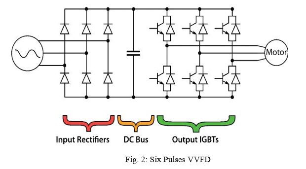
The output stage of the VVFD consists of six insulated-gate bipolar transistors (IGBTs), which turn on and off at a high frequency (8 kHz or greater), thereby modulating the DC voltage from the bus capacitors. The technology is referred to as pulse-width-modulation (PWM) and allows the drive to construct a three-phase variable AC voltage/frequency output to the elevator motor. By controlling the magnitude and phase of the voltage and frequency, the drive is able to control the motor’s torque and speed. Unlike the input diodes, current can flow in both directions across the IGBTs, allowing energy to be put back onto the DC bus capacitors.
Drives with Effects:
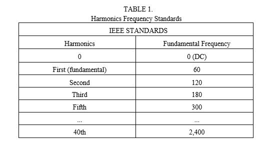
According to IEEE, harmonics are defined as “a sinusoidal component of a periodic wave or quantity having a fre¬quency that is an integral multiple of the fundamental fre¬quency.” For North American installations, the harmonics of a 60-Hz utility power supply would include the frequencies listed in Table 1.
The IEEE 519-1992 standard, titled “IEEE Recommended Practices and Requirements for Harmonic Control in Electrical Power Systems,” developed from a need to define and measure acceptable system-level voltage and current harmonics. The utility company is responsible for providing its customers with clean sinusoidal voltage with low distortion. In turn, the customers have a responsibility to not create too many current harmonics and, thus, cause undesirable voltage distortion for other customers. The IEEE 519 standard provides a basis for measuring harmonics and defines acceptable harmonic levels. Any nonlinear load’s impedance does change throughout the AC electrical cycle, and the load draws current irregularly. Since the irregular current draw is not sinusoidal, it contains harmonics of the fundamental frequency. The current harmonics act on the system impedances within a building’s electric power system. As the number and magnitude of the harmonics increases, the voltage available to other loads within the system becomes distorted. Eventually, if the distortion is high enough, the operation of other equipment can be adversely affected. In short, higher current harmonics result in a greater RMS current draw from the electric system. The increased current means the sourcing equipment (fuses, wires and transformers) of the system must be oversized. Additionally, as the harmonic currents flow through resistive impedances, additional heat is lost.
As specified in the IEEE 519 standard, the point where the utility’s electric system and the consumer’s system come together is defined as the point of common coupling (PCC). Literally, it is the first point at which the electric system is distributed within the consumer’s facility; typically the facility’s main feeder panel. The PCC is where all the loads within the consumer’s system come together to present a unified loads to the utility. This is important because some of the consumer’s loads may actually com-pensate or negate the lower power factor or high harmonics of other loads. As a result, the utility sees an aggregate of all consumer loads at the PCC. The distortion of the collective load measured at the PCC is often better than the distortion of any one individual nonlinear load.
That being said, the degree to which a load impacts the utility depends largely on the relative size and duty of that load. An example, a single 100-hp, VVFD-driven chiller running at continuous duty will have a much greater impact on the building’s electric system and utility load than a 40-hp elevator system operating at 50% duty, at best. The harmonic currents from the chiller VVFD alone could exceed the total current drawn from the elevator VVFD, making the elevator load somewhat inconsequential. However, since the facility’s main feeder panel is often hard to access by equipment contractors, a general prac-tice has been adopted to apply the terms and conditions of the IEEE 519 standard to the local accessible electrical system. This is typically the disconnect switch feeding the equipment in question. So, in practice, the PCC becomes the disconnect switch for the chiller system. Likewise, the disconnect for the elevator system is the PCC for the elevator control supplier and contractor. While this is not technically correct according to the standard (and, further, the utility would never make such a measurement), it is the accepted practice. The theory is that if the power quality at the equipment disconnect is in compliance, then the equipment can in no way negatively affect the power quality within the building. Considering an elevator is fed from an individual isolation transformer that is on the line side of the PCC. The transformer is sized based on the VA of the elevator motor (where transformer VA = FLA motor x Volts motor x 1.732). If the transformer has impedance around 5%, the resulting ISC/IL will be around 20. Acceptable TDD values would be 5% if the ratio is below 20 and 8% if at or above 20. Note, this would be considered a minimum sizing for the transformer, and the configuration would not typically be employed. Normally, the input full load amps (FLA) to the controller would be considered when sizing the transformer, which would push the VA of the transformer higher. The result is that the ISC/IL ratio would rise to approximately 25-30, and the acceptable TDD value would be 8%.
During a typical elevator cycle, energy is put into the system, stored and returned. During motoring mode, energy flows from the utility to the motor and mechanical work is done when the elevator cab moves. Additionally, both potential and kinetic energy are stored in the elevator system and returned to the drive during generating mode. Since the current cannot flow across the input rectifiers, the regenerative energy is stored in the DC bus capacitors. Traditionally non regenerative VVFDs, braking resistors have been used to rid the capacitors of the excess regenerated energy. As current flows into the capacitors, the voltage across the capacitors increases. When the DC bus voltage reaches a threshold, a resistor circuit is closed across the capacitors, and current flows through the braking resistor, dissipating the excess electrical energy as heat. The heat represents energy loss in the system, since it cannot be recovered. Braking resistors are twice as inefficient when additional energy is needed to power an air-conditioning unit to cool the control room. The ratio is below 20 and 8% if at or above 20. Note, this would be considered a minimum sizing for the transformer, and the configuration would not typically be employed.
A regenerative unit can be used in lieu of a braking resistor, and the regenerated power can be returned to the grid, where it is consumed by other building loads. Regenerated units are becoming increasingly popular, as they can dramatically increase system efficiency and lower the total cost of elevator ownership. The components of regen drives are similar to those of a six-pulse VVFD, except there is no input diode stage. The regenerative drive has DC bus capacitors and an IGBT stage used to output current into the mainline. Additionally, an inductor is used to smooth current flow and synchronize the current to the voltage and frequency of the mainline. When the voltage of the coupled DC bus reaches a threshold, the regenerative unit’s IGBTs cycle at the same frequency of the line and current flows back onto the line. It should be noted that since the regenerative unit’s IGBT’s only cycle at 60 Hz, there are significantly less switching losses during operation than the PWM operation of a VVFD. Since the regenerative IGBTs switch the current into the line in a similar manner to the diodes in a six-pulse rectifier, a regenerative unit will have similar harmonic content during regenerative mode as a VVFD. Passive Harmonic Filtering.
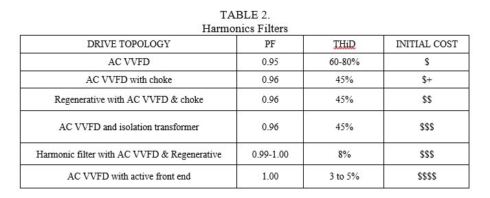
A series of low-pass harmonic filters can be placed at the input of a VVFD or regenerative unit to reduce the harmonic currents. The harmonic filter is composed of inductors and capacitors and designed such that the filter passes current at the fundamental frequency but blocks current at higher frequencies. The active front end (AFE) system is comprised of two back-to-back inverters. The first inverter synchronizes itself to the line voltage and actively rectifies the AC voltage into DC. This active rectifier stage uses an inductive capacitive filter to link to the AC line. The result is current flowing from the line in a nearly pure sine wave with low harmonic distortion; in many cases, it can be below 2% THiD. The PF Total is regulated to a value nearly 1.00 as shown in Table 2 additionally, a high-quality EMI filter in front of the system is necessary, as the active rectifier creates a high level of common-mode EMI relative to earth ground. The second inverter functions as a motor drive and controls the motor as before, independent of the front-end stage.
Because the AFE uses PWM with a high-carrier frequency, the switching losses are higher compared to the block-style commutation of the regen unit. The PWM iron losses in the AFE filter are also higher compared to those in similarly sized harmonic filters. AFE systems can only be connected to a balanced three-phase wye, center grounded electric system; delta-connected systems are not permissible. Additionally, the phase voltages should be +/-5% with respect to each other. A transformer must be used in buildings having an older delta electric system or if the phases are greatly unbalanced. An AFE exceeds the requirements of the IEEE 519 standard, but the added performance comes at a higher cost.
Inference and Recommendations:
Harmonic mitigation is possible with cost. The extra components required to mitigate drive harmon¬ics require more packaging and add upfront cost to the elevator controller. However, payback can ultimately be realized in the form of smaller electrical components, regenerative energy, utility rebates and increased operating lifetime of other system components. The IEEE 519 standard is meant as a guideline and provides goals for acceptable power quality. It is not economical or feasible that every elevator meet these requirements, as other loads within the building will have a dominating effect. In the end, a building owner or consultant will need to weigh the different drive technologies and paybacks to see if the added investment of regenerative drives and harmonic mitigation justifies the benefits.
References:
[1] Anand R and Mahesh M “Analysis of Elevator Drives Energy Consumptions with Permanent Magnet Machines”, in Proc. IEEE SEGE, Aug. 21-24 2016, pp. 186 – 190
[2] CIBSE (Chattered Institution of Building Services Department) “Guide D. Transportation structure in buildings” CIBSE (United Kingdom), London 2010.
[3] Joachim Holtz and Xin Qi “Optimal Control of Medium-Voltage Drives - An Overview” IEEE Tran. .Ind. Electron, vol. 60, no.12, pp: 5472 – 5481, Nov. 2013
[4] Harmonic Limit Compliance Evaluations Using IEEE 519-1992, S. Mark Halpin and Reuben F. Burch, IV
[5] IEEE Recommended Practices and Requirements for Harmonic Control in Electrical Power Systems, IEEE Standard 519, 1992.
Authors:
 |
Anand R started career with OTIS in 1992 and includes eight years diversification in Fujitec along with on-site work in Dublin for a period of one year on all the modern technology with commissioning and testing, worked at China and Singapore on the regenerative drive for motors with gearless machine, currently working with OTIS R&D Bangalore. He is a PhD student in Electrical and Electronics Engineering at People Education Society Institute of Technology under Visvesvaraya Technological University with research interests on machines, system integrations. |
 |
M Mahesh is in the Faculty of Electrical and Electronics Engineering, People Education Society University, having an professional experience of eighteen years and has worked on development of various power converters, feedback control design for converters and having very rich knowledge skills in Power Factor Correction Converters and Switch Mode Power Supplies He Received his PhD from National Institute of Technology, Rourkela having 20 publications with 30 citations. His feather also carries Development of 3-phase Active Power Factor Correction Converter for DPS applications along with Design of various power converters with Strong knowledge on Magnetic Design, Filters |
About the Newsletter
Editors-in-Chief

Jin-Woo Ahn
Co-Editor-in-Chief

Sheldon Williamson
Co-Editor-in-Chief
TEC Call for Articles 2023 - Advances in Charging Systems
The TEC eNewsletter is now being indexed by Google Scholar and peer-reviewed articles are being submitted to IEEE Xplore.
To submit an article click here.