

Evolution of Motors Topology in Vertical Transportation With PMSM a Boon for Industries
1. Introduction
The Eureka of Archimedes in 230 B.C when the pulley was hooked to the top with a wooden box as a cab and pulled by muscular power to the present gearless traction version with steel or glass cab pulled with electrical power emphasizes the elevator architecture came across series of rebirth. Today with the urge of smart and sustainable transportation system the elevator technology is subjected to relentless innovation in the field of control algorithm and the electric motor. The direct current (DC) motors were for years as standard type of elevator motors and with the advancement in drive technology alternating current (AC) motors especially induction motor flourished for past few years, but later with the introduction of permanent magnet synchronous motors (PMSM) technology the elevator revolution began in terms of power quality, ride quality and green energy.
2. Metamorphosis of Electric motor with the arrival of PMSM in Vertical Transportation System
Motors with dynamic calculations to guide designers have been evolved [1] to help designers, manufacturers on electric motors. In 1880, the electric motor was applied to the elevator system by Werner Siemens from then elevator industry saw metamorphism in electric motor technology. With the development of technology many changes were made to the vertical transit motors, in terms of its increased performance, reduced power consumption and size. Electronic control, introduced in the elevator industry since 1960, have incredibly increased the ride quality and also making the people movement faster. With the developments and transition in the motors starting from 1940 till date is pictorially represented in Fig.1 below. Let us summarize the motors adopted that are mainly classified into two major group’s i.e. direct start and speed control:
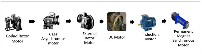
Fig 1. EVOLUTION OF PMSM MOTOR IN VERTICAL TRANSPORTATION SYSTEM [2]
2.1 Direct start or no speed control motors from the direct power supply
These motors are powered directly from the power supply, without any controls such as varying speed , other electrical parameter to adjust the acceleration of the motor but all these were limited based on the load in the car . At starting, the elevator requires maximum torque to overcome the gravity and to move the masses. The need for maximum starting torque, with reduced starting current, reduced power consumption made the elevator domain to use special motors. Following are the commonly used direct start elevator motors.
Coiled rotor motors: These motors were used in 1940 and they have high starting current i.e., up to fifteen to sixteen times the rated current, high rotor resistance and relatively low starting torque. In order to achieve required starting torque and to limit the starting current external resistors were added at starting, which was connected to the winding via phase rings, but were removed upon acceleration of the elevator. By this it was possible to achieve lower starting current parallel with increased starting torque. But the challenges in maintenance, commissioning and operation of the elevator was expensive and complex, Hence haunted for some cheaper and less complex motors.
Cage asynchronous motors with single and double winding: Cage asynchronous motors with single winding were the first caged motors found to be more robust, less complex and cheaper motors. Initially these were basically industrial motors and were not specific to the elevator application with six-pole at the start and four-pole later, with copper cage. These industrial motors, with copper cage but with some limitations such as the high starting current i.e., ten to twelve times the rated current, maximum starting torque limiting to two times the rated current and also significant variation of the motor speed typically 8 -10% of the required, and even higher in some cases. In order to overcome these drawbacks and to make elevator ride more comfortable and also to increase the accuracy of elevator at landing cage asynchronous motors with double winding came into existence, which used low polarity winding at starting and running. The high polarity was added after a certain distance from the floor, with which speed reduced consequently during each elevator landing and also to improve the ride quality, stator resistances were added, both at low polarity winding during starting and at high polarity winding while landing and were removed during acceleration and deceleration of the elevator with the aid of appropriate timers, which aid to the complex control panel operation with greater heat dissipation, particularly in elevators with higher stops because of the variation in the torque and increased stoppage heat dissipation was more due to frequent change in stator resistance.
Motors with external rotor: This was the best among all the above-mentioned motors which served as the cheaper in application. The electrical features of these motors were the same as the above motors but, differ mechanically with inner stator winding and outer rotating part, which acts as a rotor, brake and flywheel mass and was able to control the acceleration and braking. With only drawback i.e. with higher speed and duty the rotating part was getting hot and consequently affected the leveling of elevator car during landing.
2.2 Speed controlled motors
As the demand on high speed and heavy duty elevators increased due to an increase in sky risers and commercial buildings with excellent ride quality, with good levelling accuracy and easy takeoff, speed controlled motors were introduced since the direct start motors didn’t support for these applications. Below are the following speed controlled motors,
DC Motor: DC motor was the only speed-controlled motors until 1970. This was applied in elevators with the Ward-Leonard system with an M-G set to power on the motor. The speed control was achieved by varying the voltage via resistors. This system was very complex and expensive but, was able to achieve excellent ride at high speeds. Later the resistors were gradually replaced by controllers with magnetic amplifiers and later with electronic amplifiers, with the same Ward-Leonard system. These controllers, supplying the direct current (DC) motors with DC voltage high in harmonics, made the conventional DC motors with the Ward-Leonard system extremely noisy. In order to reduce the noise and the harmonics content later in the middle of 1970, the SCR based power converters provided for the direct control of the speed of DC motor by replacing the expensive and noisy motor-generator arrangements but the results obtained were not optimal.
Alternating Current Variable Voltage (ACVV) & Variable voltage and variable frequency (VVVF) Induction motors: With the significant growth in power electronics drive[3] model and readily available alternating current supply the induction machine(IM) more particularly Squirrel cage motor with ACVV drive with both at one speed and two speed gradually replaced DC motors in the elevator system. ACVV used with induction motor provided variable supply voltage but with high harmonics, the speed control was achieved by the method of sliding of the rotor, with the braking energy being dissipated in the rotor itself. Due to this IM with ACVV for elevator became noisier consequently with increased temperature, especially in high rise and heavy duty system due to this increased temperature there was uncaging of the rotor cage bars. This type of AVCC induction motor was used only in geared systems. To overcome these limitations with respect to ACVV induction motors from 1990 VVVF IM came into picture. These are the advanced ACVV IM with reinforced insulators and with efficiency of 70-80%. IM with VVVF was used with both geared as well as gearless system, irrespective of speed and also with this technology it was possible to recover the energy during braking in high duty and high rise system. Again the only drawbacks were low power factor, harmonics, bulk size and maintenance.
PMSM: As the trend on use of gearless system increased even with speed less than 1mps there was relentless innovation in the gearless system with the emergence of Permanent Magnet Synchronous Motor (PMSM) due to its high efficiency and a better power and weight ratio (power density). PMSM appear as an interesting alternative for several reasons, such as: the elimination of rotor copper losses, increased efficiency, higher power density, lower rotor momentum of inertia and the possibility of using regenerative brakes even at low speeds. The PMSM uses just 30 percent to 40 percent of the energy [4-5] of comparable induction motor or DC motor. Typically, an AC gearless low-rise elevator with a PMSM has less than a 10 HP motor, compared to motors of up to 40 HP for DC motor and up to 60 HP for induction motor. On the other hand, PMSMs have several disadvantages, such as the constant flux provided by the magnets and high costs due to the increased price of rare-earth magnets usually Neodymium-iron-boron, with more complex structure, with either internal or external rotor, but with compact size they can be easy installed in the shaft, thus eliminating the machine room. Also PMSM can generate torque at zero speed but require encoder feedback for its start and also requires software-controlled inverter for operation which is characterized by smooth rotation over the entire speed range of the motor, full torque control at zero speed, and fast acceleration and deceleration. To achieve such control, vector control techniques are used for PMSM. The vector control techniques are usually referred to as field-oriented control (FOC). The basic concept of the vector control method is to decompose a stator current into a speed field-generating part and a torque-generating part. Both components can be controlled separately after decomposition.
3. Stator fault of PMSM boon to the technology
Permanent magnet motors can provide braking torque without an external power supply during stator fault condition. i.e., shorting of stator winding. This condition can be adopted for controlling the car movement since there is a imbalance between counterweight and car by the virtue of the system. This can be done by an external relay which can short the motor phases. The braking torque can be defined through additional resistors in series with the relay. To optimize the number of contacts in the relay only two motor phases are switched. For default, the motor phases are shortened by NC contacts via the resistors. When the relay is turned on first the short circuit of the motor phases is opened and then the motor is connected to the drive. When the relay is released first the motor is disconnected from the drive and then the motor phases are shortened via the resistors as shown in Fig 2.
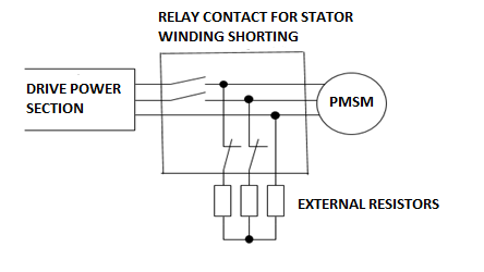
Fig 2. SHORTING OF STATOR WINDING OF PMSM ARRANGEMENT
3.1 How PMSM can emerge as ideal gearless motor in future?
Power density in turn motor size reduction, reduced torque ripple in turn reducing motor vibration and premature ware, current ripple reduction in turn smaller and less expensive passive components for filtering, improved performance of the motor control by shortening the dead-time especially in high speed elevators are the attractive features and future in making PMSM an ideal gearless motor. The above mentioned features are dependent on one factor that is high-frequency switching of PMSM [6]. Wide bandgap (WBG) semiconductors like gallium nitride and silicon carbide can serve the purpose by operating efficiently at higher frequencies. They exhibit a higher electron mobility, higher breakdown voltage i.e., above 600V, can operate safely at higher temperature impacting reduction in drive weight and heat sink thickness. Higher bandgap of 2~4eV compared to 1.5eV for silicon will emerge as the favored power semiconductor for driving PMSM motors. Discrete and integrated SiC FET bridge modules are worth consideration.
4. Inference and Recommendations
This is how the PMSM motor evolved and bought a revolution in elevator industry with its compact size, improved ride quality and effective power saving by reducing harmonics and improved power factor thus power saving in customer premises. With the help of FOC control the flux controlling is more effective especially in field weakening model which is the added advantage in providing the common platform motor from low to high rise and from low to high duty application and by applying the stator shortening method during rescue we can achieve ease of braking techniques without depending on the main power supply and also with the help of WBG semiconductor it is promising that PMSM motor will stand as ideal gearless motor for the future.
5. References
[1] B Bilgin, J Liang, MV Terzic, J Dong, R Rodriguez, E Trickett and A Emadi “Modelling and Analysis of Electric Motors: State-of-the-Art Review” IEEE Trans. on Trans Electric, 2019
[2] www.otis.com
[3] Joachim Holtz and Xin Qi “Optimal Control of Medium-Voltage Drives - An Overview” IEEE Tran. Ind. Electron., vol. 60, no.12, pp: 5472 – 5481, Nov. 2013
[4] Anand R and Mahesh M “Analysis of Elevator Drives Energy Consumptions with Permanent Magnet Machines”, in Proc. IEEE SEGE, Aug. 21-24 2016, pp. 186 – 190
[5] Anand Raghavendra Rao, and Matada Mahesh “Analysis of the energy and safety critical traction parameters for elevators” EPE Journal, vol 28, No, pp169-181
[6] Yingzhe Wu, Hui Li, Benjie Ma, Qinghai Dong, Qishui Zhon “High-frequency Model of Permanent Magnet Synchronous Motor for EMI prediction in Adjustable Speed Drive System”, in IEEE International Power Electronics and Application Conference and Exposition (PEAC) 2018, DOI:10.1109/peac.2018.8590534, Corpus ID: 57191582.
Authors:
 |
Anand Raghavendra Rao received his PhD in Electrical Engineering, Post Graduate in Electronics and Graduated in Electrical and Electronics. He is in the approval board for design review committee, has been certified in various programs like field assurance review auditing, new era of MRL lifts with latest technology from Dublin-Ireland, PM Machine technology with regenerative inverters from Hangzo – China. He has 27+ years of diversified experience in vertical transportation with research interest on PM motors, drives, energy management and system integration.. His specialized areas include New Product Development, Systems technical analysis and Process standardization He has played very key role for different standards of the code requirements for the latest Japanese technology in vertical transportation. He has more than two years of international experience at Ireland, China and Singapore. He is an IEEE Senior member and won many accolades and awards as a technical expert in the field of vertical transportation. |
 |
Nithya N, Student member in IEEE and graduate in Electrical Engineering from Siddaganga Institute of Technology in the Year 2017. She has 2.5yrs of experience in OTIS R&D Bangalore as an Electrical engineer where she worked on VFDs, PMSM motor and PID controller, currently, she is working with Epiroc mining India limited (R&D) Bangalore in collaboration with ABB and Northvolt in design of Battery powered Electric vehicle. She is also part of the SIMS (Sustainable Intelligent Mining Systems) project of the EU from Epiroc for BEVs. Her work/research includes Electricmotors, Drive, and Batteries. |
About the Newsletter
Editors-in-Chief

Jin-Woo Ahn
Co-Editor-in-Chief

Sheldon Williamson
Co-Editor-in-Chief
TEC Call for Articles 2023 - Advances in Charging Systems
The TEC eNewsletter is now being indexed by Google Scholar and peer-reviewed articles are being submitted to IEEE Xplore.
To submit an article click here.