


Recent Developments in Capacitive Wireless Power Transfer
Fei Lu, Chris Mi
San Diego State University, San Diego, CA
1. Introduction
Capacitive power transfer (CPT) technology is an effective and important alternative to the conventional inductive power transfer (IPT) [1]-[2]. It utilizes high-frequency electric fields to transfer power, which mainly owes three advantages: negligible eddy-current loss, relatively low cost and weight, and considerable misalignment performance [3]. In recent years, the power level and efficiency of a CPT system has been significantly improved, which have been suitable for electric vehicle charging applications [4]. This paper reviews the latest developments in CPT technology, focusing on two key technologies: the compensation circuit topology and the capacitive coupler structure. The fundamental working principle of the CPT system is also presented, which provides the guidelines for the future research. Based on these analyses, the applications of the CPT technology can be promoted. The structure of a CPT system in the electric vehicle charging application is shown in Fig. 1.
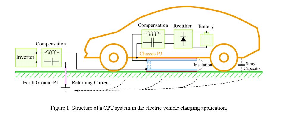
At the primary side, an inverter is used to provide ac excitation to the resonant circuit, and a compensation network can establish resonances with the capacitive coupler, which contains two metal plates. The vehicle chassis and earth ground are also involved in the power transfer process to simplify the system structure, and the circuit parameters are designed to reduce the voltages on the vehicle chassis for safe operation [5].
2. Fundamental Working Principle
To analyze its fundamental working principle, the capacitive coupler is represented by a behavior-source model [6]-[7], resulting in the equivalent circuit topology as shown in Fig. 2.
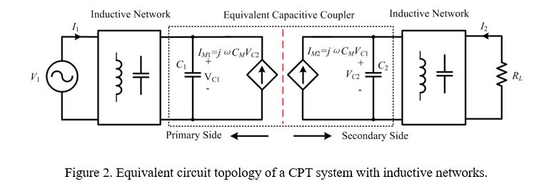
In Fig. 2, the mutual capacitance is defined as CM, and the self-capacitances are defined as C1 and C2. The active power PM transferred to the secondary side [8] is calculated as

where θ is the phase difference between VC1 and VC2. It shows that the system power is proportional to the switching frequency, coupling capacitance, and the voltages on the plates. Therefore, the key technologies in a CPT system include two parts: increasing the coupling capacitance CM through capacitive coupler design and increasing the plate voltages |VC1| and |VC2| through compensation circuit design.
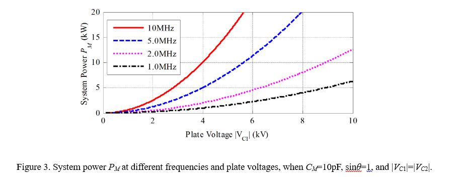
For example, when CM is 10pF, the system power PM at different frequencies and plate voltages is shown in Fig. 3. It indicates that, for an electric vehicle charging application, if 3kW power is required, the plate voltages need to be 7kV at 1MHz switching frequency.
3. Compensation Circuit Topology
Different CPT systems can be distinguished by their compensation circuit topologies. The recent compensation circuit can be classified as non-resonant and resonant topologies. It needs to be emphasized that the compensation networks in Fig. 1 are not necessarily to be resonant circuits. As long as the voltages on plates can be established for power transfer, it does not matter there are resonances in the circuit or not. The compensation circuit topologies are summarized in three categories: PWM converter based topology [9], power amplifier based topology [10], and full-bridge inverter based topology [11], in which the full-bridge inverter is the most effective way to realize a CPT system. Then, multiple compensation circuits can be developed to realize capacitive power transfer, for example series L, LC, LCL, LCLC, CLLC, etc. For example, an LCLC compensation circuit is shown in Fig. 4.
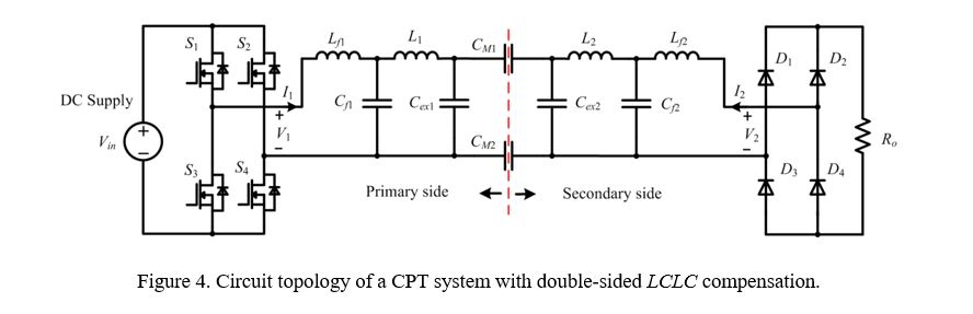
The advantage of the double-sided LCLC compensation circuit is that the system power is proportional to the coupling capacitance CM, and the system power can be regulated through circuit parameter design without affect the coupling coefficient [12]. Therefore, it is possible to maintain a high coupling coefficient for efficiency consideration while fulfilling the power requirements.
The experimental results show that it can achieve 2.4kW power transfer across an air gap distance of 15cm with 90.8% dc-dc efficiency. When there is 300mm misalignment, it can still maintain 2.1kW output power without affecting the system efficiency, which is suitable to be applied in the electric vehicle charging scenario. Compared to the conventional IPT system [13], it has much lower system cost and better misalignment performance. However, it needs to be pointed out the power density and efficiency of a CPT system is still not comparable to the IPT system, which is the future research direction.
4. Capacitive Coupler Structure
The capacitive coupler consists of multiple metal plates that are used to generate electric fields to transfer power. There are coupling capacitances between each pair of plates, and different structure of the capacitive coupler results in different coupling model. Depending on the coupler structure, there are two-plate coupler structure [5], four-plate parallel structure [12], four-plate stacked structure [6], six-plate structure [14], and repeater structure [15]. No matter how complicated is the capacitive coupler, it can be simplified as a two-port network for the circuit analysis. Generally, the capacitive coupling between the primary and secondary sides can be represented by two behavior sources as shown in Fig. 2, which is a duality to the inductive coupler model in an IPT system.
For example, in a six-plate coupler structure, there are totally 15 coupling capacitances between plates, and they can be simplified as one mutual and two self-capacitances. This coupler is the combination of the four-plate parallel and stacked structures, and it can help to eliminate the external capacitance and reduce the electric field emissions. Especially in the high power CPT system for electric vehicle charging application, the six-plate coupler can improve the system safety performance. The electric field emissions of a six-plate coupler in a 1.97kW CPT system are shown in Fig. 5.
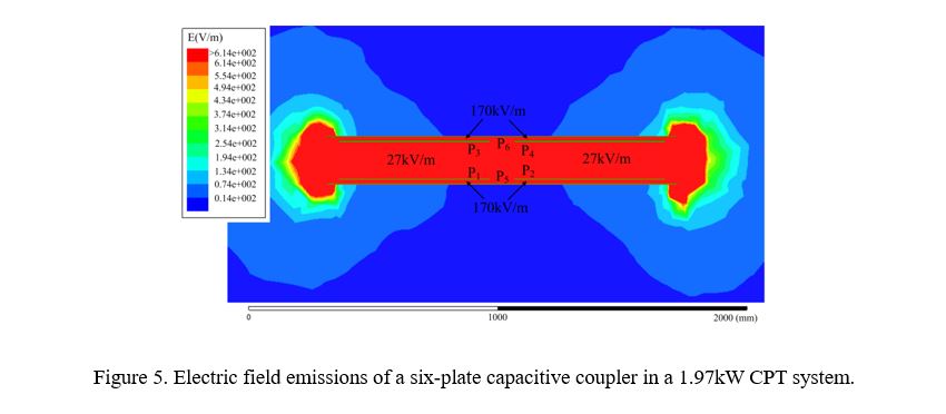
According the IEEE C95.1 standard, the electric field strength should be lower than 614V/m at 1MHz for human safety consideration [16]. It shows that although the electric field strength is 170kV/m between plates, the leakage field outside the coupler is significantly reduced by the shielding, and the safe range is about 100mm away from the coupler.
5. Conclusions
The research on CPT technology is becoming popular in recent years. This paper reviews and summarizes the latest progresses and developments in the CPT technology. The analysis of fundamental working principle shows two key technologies: the compensation circuit topology and the capacitive coupler structure. With the development of these two technologies, the system power and efficiency have been significantly improved and the safety operation range is also increased, indicating that the CPT technology has been well prepared for practical applications in the near future.
References
[1]. Kazmierkowski, M.; Moradewicz, A. Unplugged but Connected: Review of Contactless Energy Transfer Systems. IEEE Ind. Electron. Mag. 2012, 4, 47-55.
[2]. Popovic, Z. Cut the Cord: Low-Power Far-Field Wireless Powering. IEEE Micro. Mag. 2013, 2, 55-62.
[3]. Huang, L.; Hu, A.P.; Swain, A.; Kim, S. Ren, Y. An Overview of Capacitively Coupled Power Transfer-A New Contactless Power Transfer Solution. in Proc. IEEE Conference on Industrial Electronics and Applications. Australia, June 19 2013, pp. 461-465.
[4]. Dai, J.; Ludois, D. A Survey of Wireless Power Transfer and a Critical Comparison of Inductive and Capacitive Coupling for Small Gap Applications. IEEE Trans. Power Electron. 2015, 11, 6017-6029.
[5]. Lu, F; Zhang, H.; Mi, C. A Two-Plate Capacitive Wireless Power Transfer System for Electric Vehicle Charging Applications. IEEE Trans. Power Electron. 2017, in press, DOI 10.1109/TPEL.2017. 2735365.
[6]. Zhang, H.; Lu, F.; Hofmann, H.; Liu, W.; Mi, C. A Four-Plate Compact Capacitive Coupler Design and LCL-Compensated Topology for Capacitive Power Transfer in Electric Vehicle Charging Application. IEEE Trans. Power Electron. 2016, 12, 8541-8551.
[7]. Huang, L.; Hu, A.P. Defining the Mutual Coupling of Capacitive Power Transfer for Wireless Power Transfer. Electronics Letters. 2015, 22, 1806-1807.
[8]. Lu, F. High Power Capacitive Power Transfer for Electric Vehicle Charging Applications. 2017, University of Michigan.
[9]. Dai, J.; Ludois, D. Capacitive Power Transfer through a Conformal Bumper for Electric Vehicle Charging. IEEE J. Emerg. Sel. Topics Power Electron. 2016, 3, 1015-1025.
[10]. Choi, B.; Nguyen, D.; Yoo, S.; Kim, J.; Rim, C.T. A Novel Source-Side Monitored Capacitive Power Transfer System for Contactless Mobile Charger Using Class-E Converter. in Proc. IEEE Veh. Tech. Conference. May 18 2014; pp. 1-5.
[11]. Kline, M.; Izyumin, I.; Boser, B.; Sanders, S. Capacitive Power Transfer for Contactless Charging. in Proc. IEEE Appl. Power Electron. Conference. USA, March 6 2011; pp. 1398-1404.
[12]. Lu, F.; Zhang, H.; Hofmann, H.; Mi, C. A Double-Sided LCLC-Compensated Capacitive Power Transfer System for Electric Vehicle Charging. IEEE Trans. Power Electron. 2015, 11, 6011-6014.
[13]. Li, S.; Li, W.; Deng, J.; Nguyen, T.D.; Mi, C. A Double Sided LCC Compensation Network and Its Tuning Method for Wireless Power Transfer. IEEE Trans. Veh. Techn., 2015, 6, 2261-2273.
[14]. Zhang, H.; Lu, F.; Hofmann, H.; Liu, W.; Mi, C. A Six-Plate Capacitive Coupler to Reduce Electric Field Emission in Large Air-Gap Capacitive Power Transfer. IEEE Trans. Power Electron. 2017, in press, DOI 10.1109/TPEL.2017. 2662583.
[15]. Zhang, H.; Lu, F.; Hofmann, H.; Liu, W.; Mi, C. An LC Compensated Electric Field Repeater for Long Distance Capacitive Power Transfer. IEEE Trans. Ind. Appl. 2017, in press, DOI 10.1109/TIA.2017. 2697846.
[16]. IEEE Standard for Safety Levels with Respect to Human Exposure to Radio Frequency Electromagnetic Fields, 3 kHz to 300 GHz, IEEE Standard C95.1–2005, 2006.
Authors
 |
Fei Lu (S’12-M’17) received the Ph.D degree from the University of Michigan, Ann Arbor, USA, M.S. and B.S. degree from Harbin Institute of Technology, Harbin, China, in 2017, 2012 and 2010, respectively, all in electrical engineering. He is now a postdoctoral researcher and lecturer in the Department of Electrical Engineering at San Diego State University, starting from 2017. His research interests include the high-efficiency converters and emerging technologies in power electronics. His recent research focus is on the wireless power transfer for the application of electric vehicle charging and portable devices. He is working on the high power and high efficiency capacitive power transfer through an air-gap distance up to 100’s of millimeters. He is also working on the application of wide band-gap devices on WPT system to increase the system frequency. His research on the capacitive power transfer technology has received two best paper awards from the IEEE Transactions on Power Electronics. |
 |
Chunting Chris Mi (S’00–A’01–M’01–SM’03–F’12) received the B.S.E.E. and M.S.E.E. degrees in electrical engineering from Northwestern Polytechnical University, Xi’an, China, and the Ph.D. degree in electrical engineering from the University of Toronto, Toronto, Ontario, Canada, in 1985, 1988, and 2001, respectively. He is a Professor and chair of electrical and computer engineering and the Director of the Department of Energy (DOE) -funded Graduate Automotive Technology Education (GATE) Center for Electric Drive Transportation, San Diego State University, San Diego, USA. Prior to joining SDSU, he was with with University of Michigan, Dearborn from 2001 to 2015. He was the President and the Chief Technical Officer of 1Power Solutions, Inc. from 2008 to 2011. He is the Co-Founder of Gannon Motors and Controls LLC and Mia Motors, Inc. His research interests include electric drives, power electronics, electric machines, renewable-energy systems, and electrical and hybrid vehicles. He is a fellow of both IEEE and SAE. |
About the Newsletter
Editors-in-Chief

Jin-Woo Ahn
Co-Editor-in-Chief

Sheldon Williamson
Co-Editor-in-Chief
TEC Call for Articles 2023 - Advances in Charging Systems
The TEC eNewsletter is now being indexed by Google Scholar and peer-reviewed articles are being submitted to IEEE Xplore.
To submit an article click here.