


Study Methods of Wireless Power Transfer Technology in Electric Vehicle Charging
By, Chris Mi
Co-written by Subhadeep Bhattacharya and Manoj Kumar Mallela, editors of IEEE TEI Newsletter
This article is written based on the part of presentation given by Dr. Chris Mi at the Wireless Power Transfer (WPT) workshop at The University of Michigan in Dearborn, MI, March 13 2014. Dr. Chris Mi is a Professor of Department of Electrical and Computer Engineering at the University of Michigan in Dearborn.
Contrary to general belief, wireless power transfer (WPT) has been in use for a long time (Fig. 1). The microwave oven uses the concept of wireless power transfer to heat food. Laser is another method which uses similar concept as wireless power transfer. Fig. 2 shows the various methods of wireless power transfer. However, most of these methods are not designed for the transfer of electricity, especially for an Electric Vehicle (EV). So, there is a requirement to understand the methods to study the Wireless Power Transfer technology related to Electric Vehicle (EV) charging. In this context, wireless power transfer using Electromagnetic Resonance (or otherwise, inductive charging) which can transfer power over medium distance (range of millimeters to tens of centimeters) is the topic of discussion.
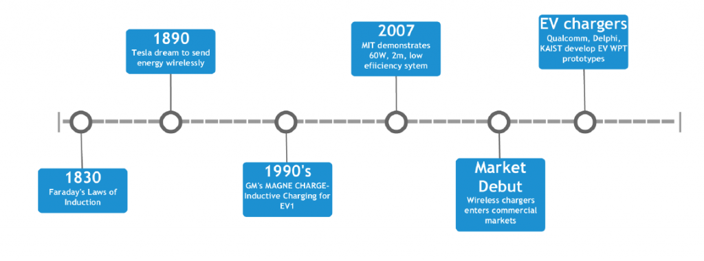 |
| Figure 1: Timeline of wireless charging evolution |
There are many challenges to achieve efficient wireless power transfer such as size, cost, and dependence on alignment, range, and efficiency. For example, unlike the traditional compact transformer, the size of the coil for WPT must be at least three times the power transfer distance. Efficiency and cost optimizations are other challenges a typical wireless power transfer system normally faces. Thus, a study of wireless power transfer deals with the physical parameters and their effects on system parameters. Also, the effect of the Wireless Power Transfer on driver safety is an important consideration in the study of the system.
 |
| Figure 2: Methods of wireless power transfer (WPT) |
Fig. 3 shows an example of a typical wireless power transfer system. The AC power from the grid is rectified to DC with necessary power-factor correction circuits. The DC signal is converted into high frequency AC and connected to the secondary through a resonant circuit using isolation transformer. The secondary output of the transformer is rectified again to feed the battery for charging purpose. The resonant circuit ideally has a number of coils whose dimensions changes with power level and purpose of EV drive.
 |
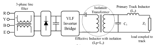 |
| Figure 3: A simple secondary controlled WPT system (taken from Covic and Boys, Proceeding of the IEEE, 101 (6), pp. 1276, 2013) |
Fig. 3 shows that Wireless Power Transfer deals with multi-disciplinary studies involving power electronics, controls, and communication. Most importantly, it requires in-depth electromagnetic design analysis. The analysis of the system can be categorized into three methods:
1. Analytical Methods:
– Equivalent circuit analysis
– Scattering-parameter analysis
2. Numerical Methods:
– Finite element analysis – electromagnetic
– High frequency structured simulation – HFSS
– Coupled field and lumped parameter analysis
3. Experimental Methods:
– S-parameter measurements and parameter identification
– Field measurements
– Power and energy emission tests
By using computer simulations, variations of the parameters such as magnetic field, total flux, and interaction of the human body to the field for different physical parameters of the system can be generated and analyzed. Simultaneously, system level simulations can be utilized to predict cost and design of switching devices and other electrical equipments needed to maintain an acceptable working condition. However, a physical design experiment is critical for the validation and optimization of the design.
 |
| Figure 4: Equivalent electrical circuit of the system |
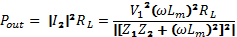
Fig. 4 shows the equivalent electrical circuit of the system. The main purpose of equivalent circuit analysis is to find the circuit parameters as mentioned above. In the equivalent circuit, the mutual inductance is only around 10% of the total inductance. The remaining inductance is due to the leakage inductance of the system. The purpose for having a series capacitance in the circuit is to cancel the leakage (or self) inductance, so that all the voltage in the primary winding is applied on the mutual inductance, thus the secondary winding receives the full input voltage with any appreciable drop. The secondary side of the circuit contains identical reactance and capacitance such that the full voltage is applied to the load device during resonance. This circuit can be used to obtain the equations of input and output voltage. The primary and secondary currents can also be obtained by knowing the values of resistances. The output power ( ), input power ( ) and efficiency ( ) of the equivalent circuit can be calculated as
 |
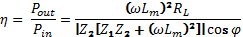 |
As can be seen, the efficiency of the system depends on mutual inductance, load resistance (equivalent to the resistance of battery), primary impedance, secondary impedance, and power factor. The system frequency is the only part of the equation which not necessarily depends on the system configurations. So, the frequency of the system plays a crucial role in determining the efficiency of the system. The efficiency of the system can vary from 20% to more than 90% depending upon the design parameters. It should be noted, however, that the calculated efficiency does not take the account of eddy current losses, cable losses, and shielding losses.
When the equivalent circuit is working under resonance condition, the power factor of the system equals to one. Looking at the efficiency equation, further simplifications can be done. Also, as the position of the system (i.e. coils) changes due to problems with misalignment and drift, the parameters (Lm, L1 and L2) will change with further impact on the efficiency of the system. Thus, the circuit has to be re-tuned so that the new system frequency takes care of the change in the system parameters. Instead of series-series resonance circuit, the series-parallel topology can also be used which reportedly has the advantage of secondary acting as current source for battery charging (Fig. 5).
 |
| Figure 5: Equivalent electrical circuit with series-parallel technology |
The calculation of the mutual impedance using analytical method is very difficult, especially if the shape of the coil is a rectangular or square. This necessitates use of numerical method as a better solution for the analysis. Also, the coupling coefficient is typically measured by indirect methods such as short circuit method and open circuit method. When the secondary is short-circuited, the current in the secondary can be measured by applying high frequency in the primary. The coupling coefficient can then be derived from the secondary current, knowing the initial primary current. During experimental analysis of the system, system parameters may not match with simulated parameters due to natural drift. The circuit is needed to be tuned to reduce the difference between the measured and simulated parameters.
A wireless power transfer network can also be analyzed as a two-port network as the charging system naturally has two inputs and two output terminals. The two-port network method describes the interaction between the input and output terminals. Although the analysis of the two-port method requires significant computation, it makes the calculation of efficiency, power transfer much more simple than using numerical methods. Also, if several resonance circuits are placed in series, a two-port network method to analyze the equivalent circuit has obvious advantages over other methods.
The important selection of the switching frequency, which effectively determines the physical parameter and efficiency of the system, depends on various factors. For low frequencies (e.g., 400 Hz) the resonant coil may become large. Also, an expected 50-100 kW power transfer effectively makes 100 kHz switching frequency range unusable due to increased switching losses in the system. Thus, a frequency of 20 kHz has been taken as reasonable for power transfer at 50-100 kW levels. Currently under study, it is estimated that 20 kHz to 80 kHz are optimal frequencies for medium and high power levels, respectively.
Now, a study on system parameters and their effect on efficiency and other factors can be improved using the system simulation tools (Fig. 6). It can be utilized to simulate the circuit for increased range and wide-range of misalignments, typically seen in real-world EV applications.
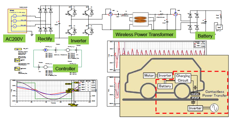 |
| Figure 6: System simulation tools (acknowledge ANSYS for this drawing) |
Various coil designs (Fig. 7) such as circular pads, flux-pipe pads, DD-DDQ bipolar pads have been proposed to improve the misalignment tolerance. The alignment abnormalities can arise from various factors such as length and height of the car and angle variations due to improper tire inflations. When the system is under proper alignment, the efficiency of power transfer is high. Any variations in alignment results in weak coupling coefficient that impacts efficiency and power transfer levels.
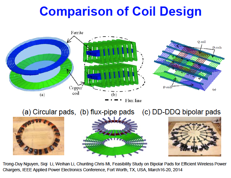 |
| Figure 7: Coil designs for WPT system (taken from Nguyen et al., "Feasibility study on bipolar pads for efficient wireless power charges, IEEE Applied Power Electronics Conference, Forth Worth, TX, March 2014) |
Different optimization objectives can be used to increase the efficiency of the system. For example, experimental analysis shows that system losses depend on the number of ferrite materials used in the system. With more number of ferro-magnetic materials to guide flux-path, one achieves better efficiency. It has been observed that there is no significant change in efficiency when more than five ferrite materials have been used. Thus, use of three ferrite materials has been taken as an optimal solution, taking cost of additional materials into consideration.
An important objective of optimizing the efficiency of the system for various operating condition is that the wireless power transfer should be efficient even for a large variation from the ideal behavior of the system. As seen from Fig. 8, (which shows the variation of coupling coefficient with coil alignment for different coil designs) for different coil designs, the coil with better response for misalignment is a good choice for the efficient power transfer in real conditions.
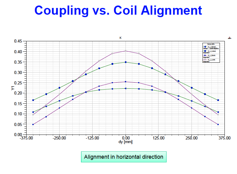 |
| Figure 8: Coupling vs. coil alignment |
This review on wireless power transfer dealt with the equivalent circuit of the wireless power transfer using magnetic resonance. Different notions of optimizing the efficiency have been discussed. As we go along with more penetrations of wireless power transfer in real-world EV battery charging, public perception will move towards using this viable technology.
About the Newsletter
Editors-in-Chief

Jin-Woo Ahn
Co-Editor-in-Chief

Sheldon Williamson
Co-Editor-in-Chief
TEC Call for Articles 2023 - Advances in Charging Systems
The TEC eNewsletter is now being indexed by Google Scholar and peer-reviewed articles are being submitted to IEEE Xplore.
To submit an article click here.