


Interesting Challenges of Designing Driver Assist Systems
Abstract— Automobiles invented more than a century ago will transform our lives again in the next decade. Driver Assist Systems(DAS) have started this transformation and the tipping point of this transformation is when they can completely take-over the ability to make decisions for automating the driving. Among other technical challenges - demand for large compute power with machine learning abilities, assess the ‘learning’ for its ability to take the decision for safe driving and optimize test cycles yet ensure to cover differences in driving behavior, traffic rules, traffic signs across geography. In this paper, we present how the industry is addressing these challenges, how are we trying to address the needs of the industry, and the eventual benefits to customers.
Index Terms— Automotive Applications, Automotive Electronics
I. INTRODUCTION
This paper puts together some of the key challenges in designing DAS and solutions that help Original Equipment Manufacturer (OEM) or Full System Supplier (FSS) in building a reliable, safe, and cost-effective product. We present our views on the benefits to OEMs and FSS based on our experience on working on similar projects. Finally, Section Ⅳ concludes the paper with final remarks and future work.
A. Minimizing time delay from perception to Action
A DAS involves several compute and signal processing blocks namely – Perception, Path Planning, Decision, and Actuation of the vehicle controls to assist in driving [1]. Each of these contribute to an eventual delay of several hundreds of microseconds to a few milli-seconds, requiring significant optimization to match a human driver response.
As per work in [2] the vehicle architectures are evolving from Distributed Electrical and Electronics (E/E) via Domain Centralized E/E towards Vehicle Centralized E/E Architecture. Looking closer at the EE architecture reveals optimizing the number of Electronic Control Units (ECUs) to fewer Domain Controller Units (DCUs) [4], minimizing in-vehicle networking traffic. A well-designed DCU based E/E Architecture could minimize in-vehicle network traffic, sharing most of the processing within different cores of the SOC. This significantly increases the complexity in software design, development, and validation.
Industry consortiums like AUTOSAR are defining Adaptive AUTOSAR architectures to standardize the approach, leaving most of it as an open system. Few OEMs are building open system platforms, fast-tracking the approach to build a cohesive solution for DCU based DAS. With years of experience in developing software for traditional ECUs, we are defining and building blocks following Service Oriented Architecture (SOA), bridging the needs of DAS in interfacing to other ECUs/DCUs. We believe this is essential for incremental steps of integration before Full automated driving becomes reality.
B. Measuring performance accuracy of Algorithms
Contrary to the traditional ECU software, many DAS control units employ machine learning algorithms for perception, path planning, and decision making. A well-designed control feedback loop is key in the former case, a well-trained model is key for the latter case. We see choosing the right data set for training the model and Validating them are challenges. Leaving them unaddressed could compromise safety guidelines described in SOTIF [4]. This requires a structured measurement process of indicators to assess algorithm performance in different driving scenarios, environmental conditions, geographical variations, and regulations.
Key Performance Indicator (KPI) based approach to validate the DAS algorithm is an industry practice. To aid KPI led validation cycle we practice a KPI Life cycle as shown in Figure 1. Each of these steps careful identification of KPIs, designing them – which involves clear identification of all the parameters to be captured during validation, Actual measurement of these parameters, Verification of the KPIs for any outliers before analyzing the computed KPIs to understand the performance of the Algorithm under test. The outcomes could define additional scenarios, additional KPIs or even enhancement of the algorithm to handle corner cases.
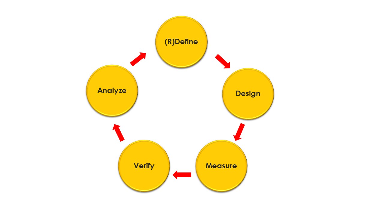
Figure 1: KPI Life Cycle
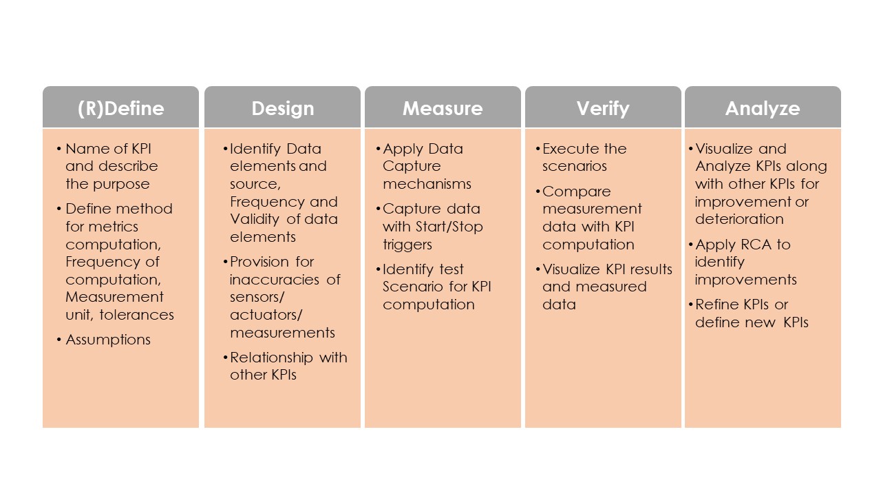
A sample list of activities to demonstrate KPI led validation are listed in Table 1.
Table 1: KPI Life Cycle Activities
The enormity of data and validation rigor requires automating most of the KPI life cycle activities and in our experience, it is as crucial as an underlying algorithm to be accurate through the entire validation process.
C. Measuring performance variation in different Geographies
Training and Validating the algorithms with data set representing different driving scenarios, environmental conditions, geographical variations can become a tough challenge [5]. Ensuring complete coverage can be a daunting task. However, it is also important to handle (to detect within the permissible time limits) exceptions, in an acceptable way without compromising the safety of occupants and others in the context.
A structured process of planning, preparing, data capture, and validation is known as Field Operation Test (FOT). With our experience we identify edge cases (corer cases with a high degree of variations) and help in route planning, optimizing the FOT trail. It is also important to capture this data (Video, LIDAR, RADAR, vehicle Bus data), along with metadata like- tagging with voice or text, cataloging either for future query or to create different sequences, to enhance the validation coverage.
We also recommend the use of synthetic data to simulate test conditions like – poor visibility due to aberration in-camera lens or dirt/mist over camera lens [6]. This in combination with other driving scenarios of over-take, cut-in, are valuable additions to the test scenarios, which otherwise are hard to simulate.
We work with local partners in chosen regions to create country-specific traffic signs, junctions, and road paints to do country-specific testing as a simulation [7]. This will save significant cost and effort in FOT. In addition, this also helps in the early detection of defects in algorithms due to country-specific nuances.
We help in building Hardware in loop (HiL) racks which can be configured for various levels of complexity of vehicle architectures, that has an Integrated Test Automation Suite iTAS, which brings connectivity from source code repository, automatic downloads of software on to ECU, automated testing of sanity and report generation.
III. CONCLUSION
In this paper, we covered only a sub-set of challenges and described a few possible solutions that could help in addressing them. In our view, a lot of work requires in defining a standard procedure to improve the coverage and deliver a satisfactory performance of the DAS function.
REFERENCES
[1] Bours, R., Rauf, K. and Kietlinski, K., 2013. A method for developing aeb systems based on integration of virtual and experimental tools. In 23rd International Technical Conference on the Enhanced Safety of Vehicles (ESV) National Highway Traffic Safety Administration (No. 13-0347).
[2] A. Bucaioni and P. Pelliccione, "Technical Architectures for Automotive Systems," 2020 IEEE International Conference on Software Architecture (ICSA), Salvador, Brazil, 2020, pp. 46-57, doi: 10.1109/ICSA47634.2020.00013.
[3] Reinhardt, Dominik & Kucera, Markus. (2013). Domain Controlled Architecture - A New Approach for Large Scale Software Integrated Automotive Systems. 221-226.
[4] ISO/PAS 21488:2019 Road Vehicles – Safety of the intended functionality.
[5] Benmimoun, M., Pütz, A., Zlocki, A. and Eckstein, L., 2012, September. Effects of acc and fcw on speed, fuel consumption, and driving safety. In 2012 IEEE Vehicular Technology Conference (VTC Fall) (pp. 1-6). IEEE.
[6] C. Galko, R. Rossi and X. Savatier, "Vehicle-Hardware-In-The-Loop system for ADAS prototyping and validation," 2014 International Conference on Embedded Computer Systems: Architectures, Modeling, and Simulation (SAMOS XIV), Agios Konstantinos, 2014, pp. 329-334, doi: 10.1109/SAMOS.2014.6893229.
[7] Z. T. Kardkovács, Z. Paróczi, E. Varga, Á. Siegler and P. Lucz, "Real-time traffic sign recognition system," 2011 2nd International Conference on Cognitive Infocommunications (CogInfoCom), Budapest, 2011, pp. 1-5.
AUTHORS
 |
Nagesh Shenoy, Heads Automotive Electronics practice for Tech Mahindra at Bangalore. His interest areas are System Architecture, Functional safety (ISO-26262), and ADAS. During his career, he has designed several AUTOSAR Complaint safety-critical systems. In recent years he is working on building systems complaints to Adaptive AUTOSAR. He has two patents to his credit He has a Master's degree in Digital Electronics and Communication from the National Institute of Technology, Suratkal, India. His email address is Nagesh.shenoy@techmahindra.com |
 |
Sateesh Kalidas, is an Automotive Electronics Engineer specializing in Infotainment for Tech Mahindra at Bangalore. His interests are in Software Architecture, HMI, and Open-source. During his career, he has been part of multiple Infotainment series productions for HMI as a software architect. He has a Bachelor’s degree in Electrical and Electronics Engineering from University Visveswaraya College of Engineering, Bengaluru, India. His email address is Sateesh.kalidas@techmahindra.com |
About the Newsletter
Editors-in-Chief

Jin-Woo Ahn
Co-Editor-in-Chief

Sheldon Williamson
Co-Editor-in-Chief
TEC Call for Articles 2023 - Advances in Charging Systems
The TEC eNewsletter is now being indexed by Google Scholar and peer-reviewed articles are being submitted to IEEE Xplore.
To submit an article click here.