

Electric Drive Power Electronics: An Overview
By: Chris Whaling
This is the first part of a series of articles on the technologies, economics and trends that drive the development of hybrid and all-electric traction drive power electronics. This article provides an overview of traction drive power electronics and forms a basis for future articles on power electronic cost analysis and trends in demand and supply of solid state device technologies for electric traction motor-drive vehicles. Key technical information reported in these articles was developed during the course of research projects funded by the U.S. Department of Energy (DOE), Vehicle Technologies Office. The author specifically thanks Steven Boyd and Susan Rogers, Technology Development Managers for Power Electronics and Electric Motors, at the Vehicle Technologies Office, within the Energy Efficiency and Renewable Energy (EERE) Program at the U.S. DOE for permission to publish information here.
Historically, electric power has been used in vehicles for electric accessories, such as power windows, entertainment systems, dashboard instruments, air conditioning, seat-heaters, and other accessories. Today, cars are being manufactured that use electric power not only for electric accessories but also for propulsion systems. Such electrified vehicles look quite similar to gasoline-propelled cars but have significant technology and engineering advancements under-the-hood, especially as it relates to power electronics. In an electric-motor-only propelled car, the electrical motors are used to power the wheels and the power for the motors is obtained from batteries. A power electronic device commonly referred to as an inverter is used to convert the DC power from the battery to AC power (at a required voltage and frequency) for the motor. A second inverter may also be used to convert AC from the generator to DC to recharge the batteries through regenerative breaking (called the generator inverter). A converter is part of the traction drive power electronics unit and is used to “step-up” (increase voltage) or “step-down” (decrease voltage) to match the EVs’ high-load or light-load sources.
Electrified vehicles come in three major types: i) hybrid architectures that run on electric traction drive motors and gasoline engines, commonly known as hybrid electric vehicles (HEVs); ii) plug-in architecture vehicles that run on electric-traction drive power and that can also have a gasoline propulsion engine for performance assist, or for propulsion power sharing, with a battery that can be charged from AC electric outlets at home (or fast-charge stations at automobile dealerships and other controlled locations), commonly known as plug-in hybrid or “extended range” electric vehicles (PHEVs); iii) cars running exclusively on electric power, commonly known as electric vehicles (EVs). All these types of vehicles must use high voltage power electronics which are solid state devices, for their traction drive motors.
The design of the traction drive inverter is determined by the application’s specific drive cycle performance needs, which in turn are affected by many variables such as operating temperature, peak and continuous power, size and weight. Each of these performance requirements in turn drives cost. Most automotive application inverters have a maximum rating in the 600V to 1200V range. Power and frequency (measured in Hertz, or Hz) are managed by hardware embedded as integrated circuits that make up the “brains”, or power control units (PCU). The PCU manages the inverter’s operation across the vehicle drive cycle regime. Although most current inverter designs incorporate both the motor inverter and generator inverter into the traction drive inverter unit, some hybrid architectures may only include the motor inverter in the primary inverter unit. In this case, the generator inverter would be in a separate assembly that would still be a component of the overall hybrid system PCU.
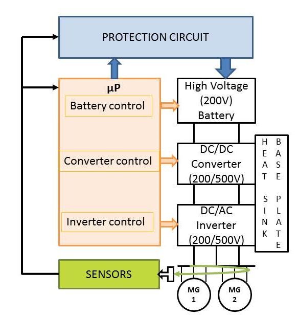
Figure 1: Layout of electric drive vehicle traction power electronic system
Figure 1 shows a block diagram of a typical electric-drive vehicle traction drive power conversion unit, along with some of the major components. The power conversion unit contains mainly of three components- solid state switches IGBTs (Insulated Gate Bi-Polar Transistors) which convert power from DC to AC or vice versa, the “brain” of the power conversion device also known as PCU and other accessories such as the thermal management system, power distribution system, etc. The power conversion is carried out in two stages i.e., there is a conversion stage which is performed by a DC/DC boost converter that steps up the voltage from the battery to the values required by the inverter. For example in Toyota Prius [1], the boost converter steps up voltage from around 200V to about 650V (maximum). The next stage, which is the inversion stage, converts the output DC voltage of the boost converter to AC voltage and frequency required to drive the electric motor.
The inverter assembly is housed in a casing with a cold plate base, and has integrated DC link capacitor as well as the corresponding driver board and PCU. The driver board contains IGBT drivers which provide high levels of gate current for short periods of time so as to turn on and turn off the devices. The heat-sink/cold plate is a passive cooling device that absorbs heat from the power electronics (IGBT devices) and then dissipates it to the environment. Generally, there is also a thermal management keeps the operating temperature within the specified limits for the power electronics, usually by using liquid coolant and the housing may include integrated cooling channels. The PCU consists of microprocessor which controls the charging/ discharging of batteries and torque or speed of the electric motor. The PCU sends appropriate command signals to the driver board so that the IGBTs are turned on or off to achieve the desired motor torque/speed and battery state of charge. Like the inverter assembly, the DC/DC converter is a separate assembly which also has power carrying device (IGBT), PCU, drive board, thermal management system, heat-sink, etc. In addition to these major components the inverter and converter assemblies include:
• Sensors: to measure voltage and current;
• Protection circuit: to protect against over-voltage, over-current and damage caused by thermal run away or hotspots;
• Filter and snubber circuits: DC link capacitor that is used to smooth the DC link voltage and smoothing capacitor used to reduce AC output voltage variation, an LC filter to reduce harmonics in AC current. The snubber-capacitor suppresses the voltage transients that the IGBT might experience when the current in the inductive circuit changes.
• Connectors and bus bars: Used to transfer power from each stage and to distribute to the motor and battery.
All these components together form the core electric traction drive power electronics. Although there are some variations in the topologies used by different manufacturers, the core power electronic components and the structure are quite similar.
As described in this article, power electronics are one of the major set of components in any electrified transportation vehicle and consist of many sub-components. The Figure below shows the cost breakdown of a typical hybrid system. This information will be discussed in more depth in the next article in the series.
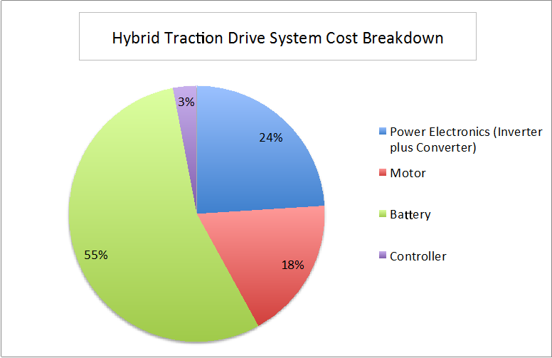
Source: Synthesis Partners, LLC (2011)
A typical hybrid system includes a dual inverter unit, the battery, motor and controller. The power electronics (inverter plus converter) make up 24 percent of the cost of the system. The other system components and their cost shares of the total hybrid system are the motor (18 percent), battery (55 percent) and controller (three percent) which could As a result, power electronics significantly impact the cost and performance of the HEV and EV vehicles. [2].
In the next series of articles, we will examine the trends in power electronics costs for electric traction drive vehicles, future developments in the power electronic device technologies and the potential for leap-ahead innovations in the form of manufacturing high-performance, competitively-priced innovative products.
References
1. Toyota “Innovations – Technology file”, website: http://www.toyota-global.com/innovation/environmental_technology/technology_file/hybrid.html
2. “Technology and Market Intelligence: Hybrid Vehicle Power Inverters Cost Analysis, Prepared for the Department of Energy by Synthesis Partners, LLC, Contract Number: DE-DT0002121, July 2011.
 Christopher L. Whaling is co-founder of Synthesis Partners, LLC, a private business and technology analysis company based in Reston, VA. Mr. Whaling has lead assessment teams in all source research, analysis and delivery of technology and market intelligence decision-support products for 20 years. Recently, Mr. Whaling refined and implemented Natural Language Processing (NLP) technology to produce beta-level, scalable decision-support systems. Mr. Whaling has been invited to present analysis products, forecasting techniques and outcomes at the US National Intelligence Council (NIC), the Society for Competitive Intelligence Professionals (SCIP), the Washington Institute for Operations Research and Management Sciences (INFORMS), and the US Department of Energy’s Oak Ridge National Laboratory. You may reach Christopher atcwhaling@synthesispartners.com.
About the Newsletter
Editors-in-Chief

Jin-Woo Ahn
Co-Editor-in-Chief

Sheldon Williamson
Co-Editor-in-Chief
TEC Call for Articles 2023 - Advances in Charging Systems
The TEC eNewsletter is now being indexed by Google Scholar and peer-reviewed articles are being submitted to IEEE Xplore.
To submit an article click here.